



How to Match LED Strip Width to Profile Inner Width
Measure the strip PCB width, then pick a profile whose inner width clears it by about 2 mm. A 10 mm strip takes a 12 mm channel. Includes the real inner-width spread across 219 profiles and why outer width is not a fit dimension.
Three width figures decide whether a strip fits, and catalogs rarely say which one they are quoting. Outer width is the silhouette. Physical inner width is the flat floor between the channel walls. PCB width is the strip size the body is built for. We quote PCB width — a 5 mm strip pairs with a 5 mm profile — and the channel around it is wider.
Mix those three up and the strip arrives too wide for the channel, or the profile arrives twice the size you needed.
What does the width figure on a profile actually measure?
Take one profile apart. HL-A086 is 10 mm wide, 60 mm tall, and takes a 5 mm strip. Its dimension drawing shows three numbers that matter:
| Figure | Value | What it is |
|---|---|---|
| Outer width | 10 mm | The visible silhouette once installed |
| Physical inner width | 8 mm | The floor between the channel walls, from the section drawing |
| PCB width (quoted) | 5 mm | The strip the body is designed around |
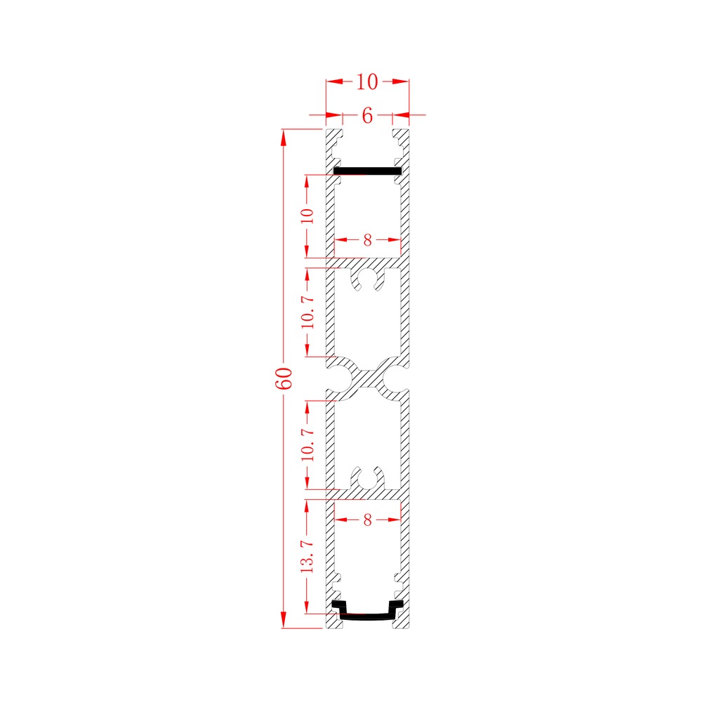
The channel is 8 mm; the profile is sold as a 5 mm profile. That 3 mm gap is the clearance — enough for the strip to seat flat without binding, and for the adhesive to make full contact with the aluminum.
This is why "a 10 mm profile" means nothing on its own.
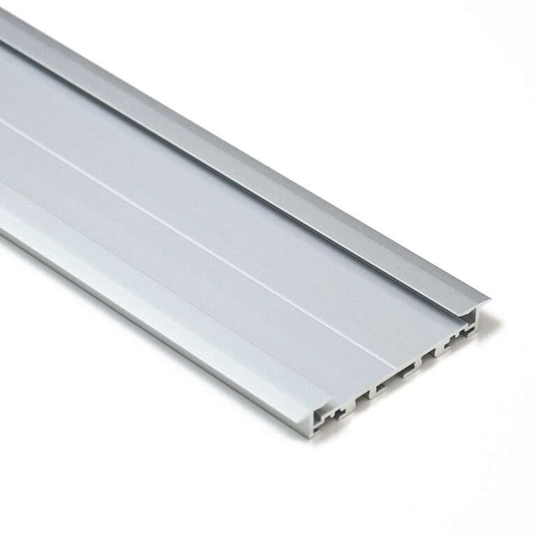
Why the outer width tells you nothing about fit
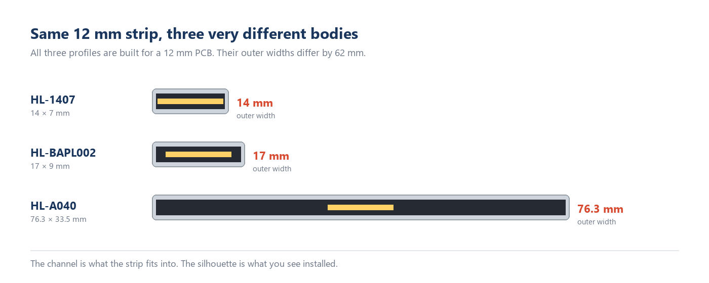
Three profiles in our range are all built for the same 12 mm strip:
| Modelo | Outer width × height | PCB width | Mounting |
|---|---|---|---|
| HL-1407 | 14 × 7 mm | 12 mm | surface |
| HL-BAPL002 | 17 × 9 mm | 12 mm | recessed |
| HL-A040 | 76.3 × 33.5 mm | 12 mm | suspended |
Same strip, 62 mm difference in outer width. One is a 14 mm sliver under a shelf; the other is a 76 mm architectural body for a suspended run. If you had ordered by outer width, you would have picked a body four times too big — or one that cannot hold the strip at all.
Outer width answers a different question: how much visual weight will this have in the room? It belongs in the design decision, not the compatibility check.
How much clearance is already built in?
Published guidance says to allow 1–3 mm between the strip and the channel. That guidance is written for the physical inner width, because an extruded channel is a raw dimension.
When a profile is sold by PCB width, the clearance is already inside that number. HL-A086 is the worked example: 8 mm channel, 5 mm quoted — 3 mm of room, at the top of the usual range.
So the rule depends on which figure you are reading:
| If the catalog quotes | Then |
|---|---|
| Physical inner width | Choose 1–3 mm above your strip width. A 10 mm strip takes an 11–13 mm channel. |
| PCB width (our listing) | Match it to your strip. A 10 mm strip takes a 10 mm profile. |
| Only outer width | Ask for the section drawing. Do not guess — the error is 60 mm, not 2 mm. |
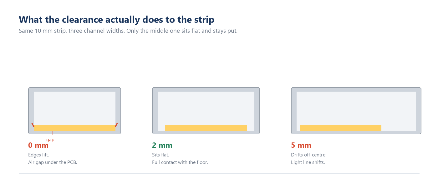
Either way, the same physics applies: the backing adhesive is the thermal path between the LEDs and the aluminum, so it has to lie flat across its full width. A channel at exactly strip width lifts the PCB edges and leaves an air gap underneath. Heat has nowhere to go, and the adhesive degrades faster.
Which PCB width goes with which strip?
The same PCB width spans an enormous range of outer sizes — that is the whole argument in one table:
| PCB width | Perfis | Outer width span | Example |
|---|---|---|---|
| 5 mm | 4 | 10 – 83 mm | HL-A086 (10 × 60 mm) |
| 12 mm | 31 | 14 – 76.3 mm | HL-1407 (14 × 7 mm) |
| 16 mm | 7 | 19.6 – 66 mm | HL-BAPL034 (19.6 × 17.8 mm) |
Wider bodies take 20 mm PCB and above — 105 profiles, up to 264.6 mm in outer width. The 12 mm group is the largest single block, because 10 mm and 12 mm strips are what most projects buy.
One more thing worth knowing: a silicone-sleeved strip adds thickness, not width. It usually clears the same PCB width but sits closer to the diffuser, so check the headroom as well as the width.
What happens when a wide channel holds a narrow strip?
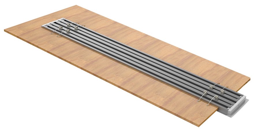
A wide body with a single narrow strip is the most common specification error we see, and it does not show up until the light is on.
The visible light line is set by the aperture — the opening the diffuser covers — not by the strip. Put a 12 mm strip into a 76.3 mm body such as HL-A040 and the lit portion occupies a fraction of the aperture. The result is a wide diffuser panel that is bright in the middle and dim at the edges, which reads as a soft gray band rather than a crisp line.
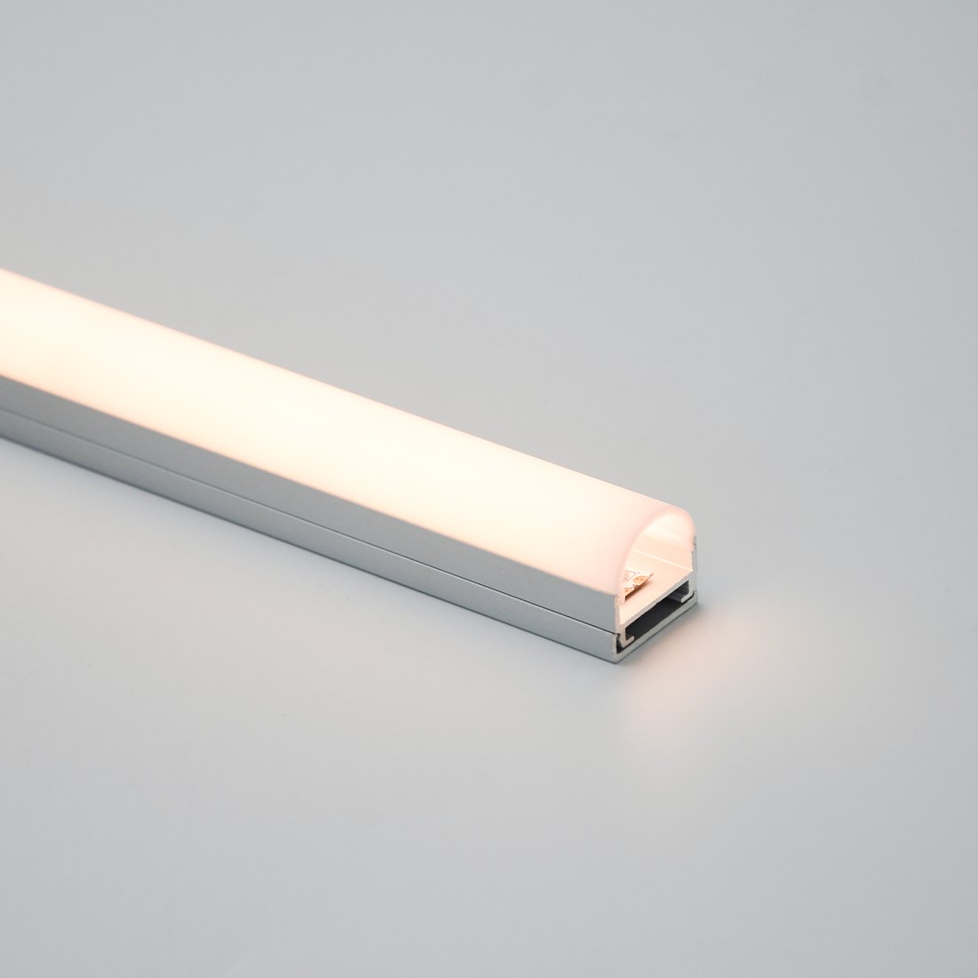
There are three honest ways to fill a wide body: a two-row or multi-row strip, two separate strips run side by side on their own circuits, or a wider board if the output has to be even across the full aperture.
The wrong fourth option is to accept the dim edges and hope the eye averages them out. At a distance it does. At two meters, on a matte wall, it does not.
Does depth matter more than width?
For dot visibility, yes — and this is where the product title misleads a second time. Overall height is not cavity depth.
Three profiles in our range share a 12 mm PCB width and differ in height:
| Modelo | PCB width | Outer width × height | Cover |
|---|---|---|---|
| HL-1407 | 12 mm | 14 × 7 mm | PC |
| HL-BAPL002 | 12 mm | 17 × 9 mm | PC or PMMA |
| HL-BAPL002L | 12 mm | 17 × 13.7 mm | PMMA lens |
All three take the same strip. At 7 mm overall height the diffuser sits close to the diodes and an SMD strip will usually read as a row of points; at 13.7 mm there is more distance for light to mix before it reaches the cover. The effect compounds with LED pitch and cover type, which is why a shallow body paired with a high-density or COB strip can still produce a continuous line.
Do not infer cavity depth from the model name or the overall height. Ask for the section drawing: you need the distance from the strip floor to the underside of the diffuser, which is drawn but rarely in the title.
A reverse method: start from the light line
Most guides assume you already bought the strip and are hunting for a channel. On project work the order is often reversed, and it is a better way to specify.
Start with the width of the line you want to see on the surface. That sets the aperture. The aperture sets the body. The body sets the PCB width it will take, and that then constrains which strips are eligible. That order prevents a strip chosen for its output from forcing a body that is visually wrong for the room.
Checking a profile before you commit
Four things to confirm, in this order: which width figure the listing quotes — outer, inner, or PCB; the strip thickness, including any coating or sleeve, against the available headroom; the cavity depth, judged against the strip's LED pitch; and a sample length — two meters of profile and strip is cheaper than a re-order.
Every dimension quoted here is the published figure for that model and can be checked on its product page in the profile range, where the section drawing sits beside the specification. If you are matching a strip you already own, send the PCB width and we will confirm which profiles are built for it.
PERGUNTAS FREQUENTES
Related links

We design and supply LED aluminum profiles and linear lighting — over 200 profiles with matched diffusers and fittings, serving customers in more than 100 countries since 2007.
Engineering Lead · Reviews every dimension, extrusion section and installation step for technical accuracy before publication.
Related reading
Send the strip width, the run length and the destination — we will match the profile, the diffuser and the fittings, and quote within 1 business day.
Start your inquiry