



How to Read an Aluminum Profile Drawing
Vijf afmetingen op één deel, en slechts twee daarvan passen bij jouw strook. Wat elke afmeting aangeeft, aan de hand van onze eigen tekening HL-A065, en welke het vaakst door elkaar wordt gehaald.
A section drawing of a recessed LED profile usually carries four or five numbers, all in millimeters, with no labels. Two of them are what you need to select the profile. One is the number people mix up, and getting it wrong is why a strip arrives that will not fit.
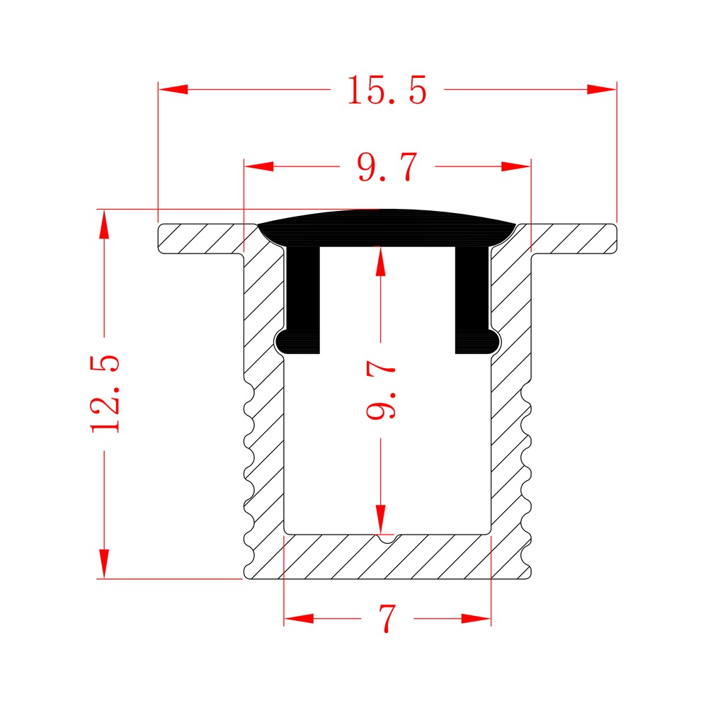
What are the five numbers on a section?
Take HL-A065 as the example: a recessed body, 15.5 × 12.5 mm, taking a 6 mm strip. Its drawing carries five dimensions.
| Number on the drawing | What it measures | What it decides |
|---|---|---|
| 15.5 | Buitenbreedte | How wide the slot has to be; visual weight |
| 12.5 | Buitenhoogte | How deep the slot has to be |
| 9.7 (horizontal) | Opening between the cover grooves | How wide the light aperture reads |
| 9.7 (vertical) | Internal cavity height | How far the strip sits below the cover |
| 7 | Strip channel width at the base | Which strip will physically fit |
The first two are the envelope. The middle two are optics. The last is compatibility, and it is the one that stops an order.
Which number is the PCB width?
Not the 9.7, and not the outer width. It is the 7: the internal channel at the base, where the strip sits.
That creates a second confusion, because the product page says 6 mm for this profile, not 7. Both are correct, and they describe different things.
- 7 mm is the channel: the physical gap between the base walls.
- 6 mm is the strip the body is designed around: the PCB width we quote.
The 1 mm difference is clearance. A 6 mm PCB in a 7 mm channel leaves room for three things. The adhesive needs some, the strip has to lie flat without force, and the solder pads at the ends often run wider than the board.
So a listing that says "10 mm" could mean either. In our listings the figure is the PCB width, and the channel around it is wider. That is why the drawing and the product page do not contradict each other. They answer different questions.
Why does that matter in practice?
Because a strip 1 mm wider than the channel does not fit neatly. Three things happen.
- It sits proud instead of flat. The adhesive contacts along a line, not a face.
- The cover will not seat. A wedged strip lifts the edges, right under the diffuser groove.
- The ends will not close. Solder pads and connectors add width where the end cap sits.
A lost thermal path is the failure described in the heat articles, arriving from a dimension error, not a design error.
A 6 mm strip in a 7 mm channel is comfortable. An 8 mm strip in the same channel is not a tight fit. It is the wrong profile.
What about the two 9.7s?
They are not the same dimension, even though they carry the same number on this drawing.
The horizontal 9.7 is the opening between the two cover grooves: the width of the light aperture as seen from below. It is an optical dimension, and it sets how wide the line of light reads.
The vertical 9.7 is the cavity height: the distance from the channel floor to the underside of the cover. It lets light from adjacent diodes mix before it reaches the diffuser. A shallow cavity shows dots. This one has enough depth for a 6 mm strip behind an opal cover.
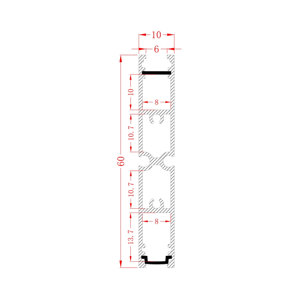
Two dimensions, same figure, different jobs. On HL-A092 the same pair reads 35 and 6: one envelope, one optic. That happens because the section was drawn to those proportions, not because one of them is a mistake.
What about tolerances?
A drawing without tolerances describes a shape, not a product.
Three categories matter on an extrusion, and suppliers usually tabulate them separately.
Cross-sectional dimensions. The five numbers above, each with a permitted deviation. These are tied to the size of the section: a 15.5 mm width and a 76 mm width do not carry the same allowance.
Form tolerances. Straightness along the length, twist of the section, flatness of a face. These do not appear on the section at all, and they decide whether a long run looks straight or wavy.
Cut length and end squareness. Introduced by cutting, not by extrusion. A body can sit inside every cross-sectional tolerance and still leave a gap at a joint, because the end was not cut square.
The practical point: a dimension on a drawing is a nominal value, and the tolerance is what you get. If a project depends on a specific fit, state the tolerance. Do not assume it.
What is not on the drawing but matters?
Four things, all of which affect whether the installation works.
Alloy and temper. The drawing shows a shape; the material is called out separately. Ours is 6063 throughout.
The cover. The section accepts a cover in a groove, but which cover, whether clear, frosted, opal or a lens, is a separate decision. It changes the light more than any dimension on the drawing.
The accessories. End caps, clips, connectors. Whether a connector exists for this section is not visible in the section itself. For HL-A065 it does not, because that section is meant for short runs.
The length. Our profiles come in any length up to 4 m, cut to your size. That figure is not on a section drawing, and it determines how many joints a run will have.
How do you check a drawing before ordering?
Five steps, in this order.
- Find the channel width: the number at the base of the section, not the outer width, not the aperture.
- Compare it with the PCB width of your strip, allowing 1–2 mm clearance.
- Check the outer height against the slot depth you can cut. A 12.5 mm body needs 12.5 mm of depth.
- Check the aperture against the look you want. A 9.7 mm opening reads as a narrow line, a 40 mm opening as a band.
- Ask which accessories exist for that section, because the drawing will not tell you.
Our bereik lists outer width, outer height and PCB width for all 219 profiles. Steps one to four can be done from the listing before opening a PDF. When a drawing is ambiguous, the contact page is faster than guessing. Send the strip width and the depth available, and we will name the section.
Is the inner width the same as the PCB width?
On our listings, no. The quoted figure is the PCB width the body is built around, and the physical channel is wider. In some other catalogs the figure is the channel width. Always check which one a listing means before comparing two products.
What does the second 9.7 on the drawing mean?
The vertical one is the cavity height: the distance from the strip to the cover. It sets how much the light mixes, and therefore whether dots are visible at close range.
Do I need the drawing if I already have the model number?
It helps for two things: confirming the channel against your strip, and confirming the depth against your slot. The model number tells you which profile. The drawing tells you whether it fits your detail.
Why are there no tolerances on my drawing?
Because a section drawing and a specification drawing are different documents. A catalog section drawing shows geometry. A manufacturing drawing carries tolerances, alloy, temper and inspection requirements. If a project depends on a fit, ask for the second kind.
Can I use a photograph instead of a drawing?
To start a conversation, yes, with a scale in the frame. To order, no. A photograph cannot tell you the channel width or the wall thickness, and those are the two figures the order depends on.

Wij ontwerpen en leveren LED-aluminiumprofielen en lineaire verlichting — meer dan 200 profielen met bijpassende diffusers en armaturen. Sinds 2007 bedienen wij klanten in meer dan 100 landen.
Geef de strookbreedte, de lengte en de bestemming door — wij zoeken het juiste profiel, de juiste diffusor en de juiste bevestigingsmaterialen uit en sturen u binnen 1 werkdag een offerte.
Dien uw aanvraag in