



How to Install Recessed Profiles in Drywall
The slot is cut to the body, not the aperture. Sizing steps from our own section drawings, where the driver goes, and the four mistakes that show after paint.
A recessed profile in drywall takes three operations, in a fixed order. Cut the slot to the body. Fix the body to structure. Close the board over it. Failures that surface months later almost always come from wrong order, not from the profile. Think of a crack along the aperture, or a wavy line.
What size does the slot have to be?
Two figures, both from the section drawing, not the aperture.
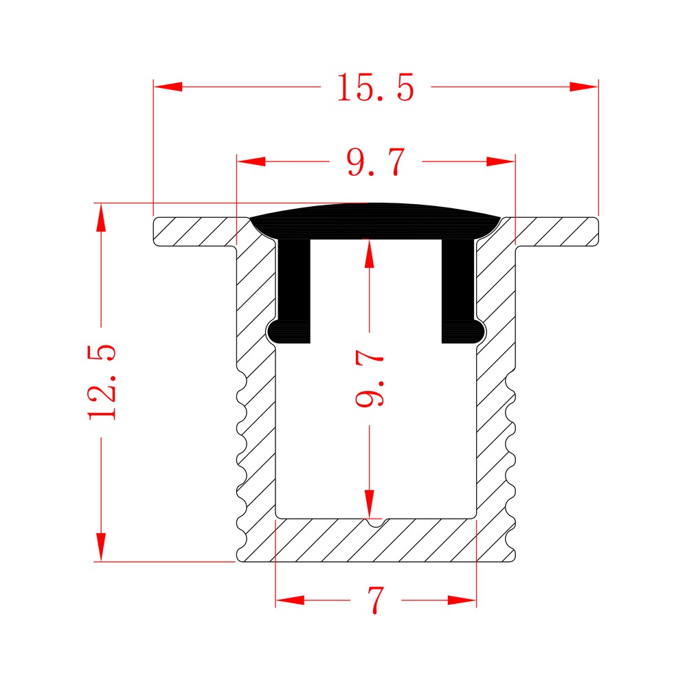
Slot width equals outer width, within 1 mm. Not a generous slot: a tight one. Our installation note for plaster-in bodies puts slot-to-body width difference within 1 mm. Aluminum wings on both sides must meet the board closely enough for compound to bridge.
A slot 2–3 mm wide leaves a gap filler cannot carry, and it cracks along that line, not at the wing. A tight slot also keeps the body level while screws go in, the second thing the note asks for.
Slot depth equals outer height, so the diffuser sits flush with the finished face.
Three examples from our range, all with sections on product pages:
| Modèle | Outer W × H | Strip (PCB) | Slot to cut |
|---|---|---|---|
| HL-A065 | 15.5 × 12.5 mm | 6 mm | ~17 × 12.5 mm |
| HL-BAPL067-F | 10.3 × 10.3 mm | 8 mm | ~12 × 10.3 mm |
| HL-A092 | 35 × 6 mm | 4 mm | ~37 × 6 mm |
The third deserves a note. A 6 mm body needs a 6 mm slot, so the board must be at least that thick. Otherwise the body sits in a rebate cut into its back. A shallow body is not automatically easier. It moves the constraint from depth to board thickness.
Which order: fix first, or board first?
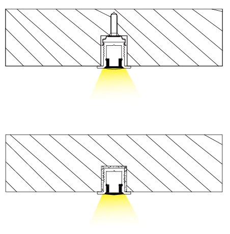
Our installation note follows this sequence:
- Set out the line on the substrate, not on the board that covers it.
- Fit the body into the pre-cut slot, keeping it level along its length.
- Drive screws through the wings into the board and its backing. Stop where the wing holds, not where the screw will travel further.
- Apply compound over aluminum wings on both sides, so body and board become one surface.
- Tape the joint as you would any drywall seam, then sand and paint.
- Fit strip and cover after finishing.
Mind the order of steps 3 and 4. Compound grips the wing, so it must be flat and firmly held before any filler goes on. A wing distorted by over-tightening leaves a hollow behind the compound. Cracks start there.
Board first, then cut a slot, suits a retrofit where the ceiling is closed. It is harder to keep straight over a long run, with no continuous reference. On a new ceiling, fitting the body first is faster and straighter.
What holds the body before the plaster?
Two options differ in how much adjustment they leave.
Clips hold the body in the slot and allow small movement before locking. This is the practical choice on an uneven substrate: clips absorb the variation.
Screws through the flange are more rigid, with no adjustment. Use them where the slot is cut true and the substrate is flat.
Both must anchor into structure, not board alone. A body fixed only to plasterboard moves with the board, and the aperture joint cracks at the first heating season.
Our ceiling collection runs to 20 profiles, and each section drawing shows the fixing points. For a recessed body, that drawing is the installation instruction. Fixing locations belong to the section, not to an afterthought.
Where does the driver go?
Decide this before the ceiling closes, not after.
Three arrangements, ordered by how often they work.
In the ceiling void, within reach of a hatch or panel. The usual answer on a plasterboard ceiling over a joist space.
In a dedicated compartment built into the ceiling: a small box with removable lid, finished flush. Use it where the void is shallow or inaccessible.
Remote, in a plant room or cupboard, with a low-voltage cable to the profile. Practical only where the run is short enough that voltage drop stays small.
The failure mode is specific. The driver sits where it was left, the ceiling closes, and access comes only through the aperture. On a narrow section, access may be impossible.
What goes wrong?
Five failures, in the order they appear.
The slot is cut to the aperture. The board edge then sits on the diffuser, which will not seat. Fix it by opening the slot after painting.
The wing fixes to the board, not to anything behind it. It is the most common complaint and the least to do with the profile. A wing that moves with the board cracks along its length within one season.
Screws are over-tightened. Our installation note is explicit: control the tightening force, or the body distorts and the cover no longer seats. A distorted wing cannot be filled flat, and a distorted channel cannot hold the diffuser. This mistake damages the product itself, not the joint.
The board is thinner than the body is deep. The profile stands proud, or the body back breaks through the far side. Check board thickness against section height before ordering, not on site.
The cable is left in the wrong place. The strip feeds at one end, and the cable must reach it with slack. A cable that stops 200 mm short means a ceiling repair.
What about the cover and the strip?
Both go in after finishing, deliberately.
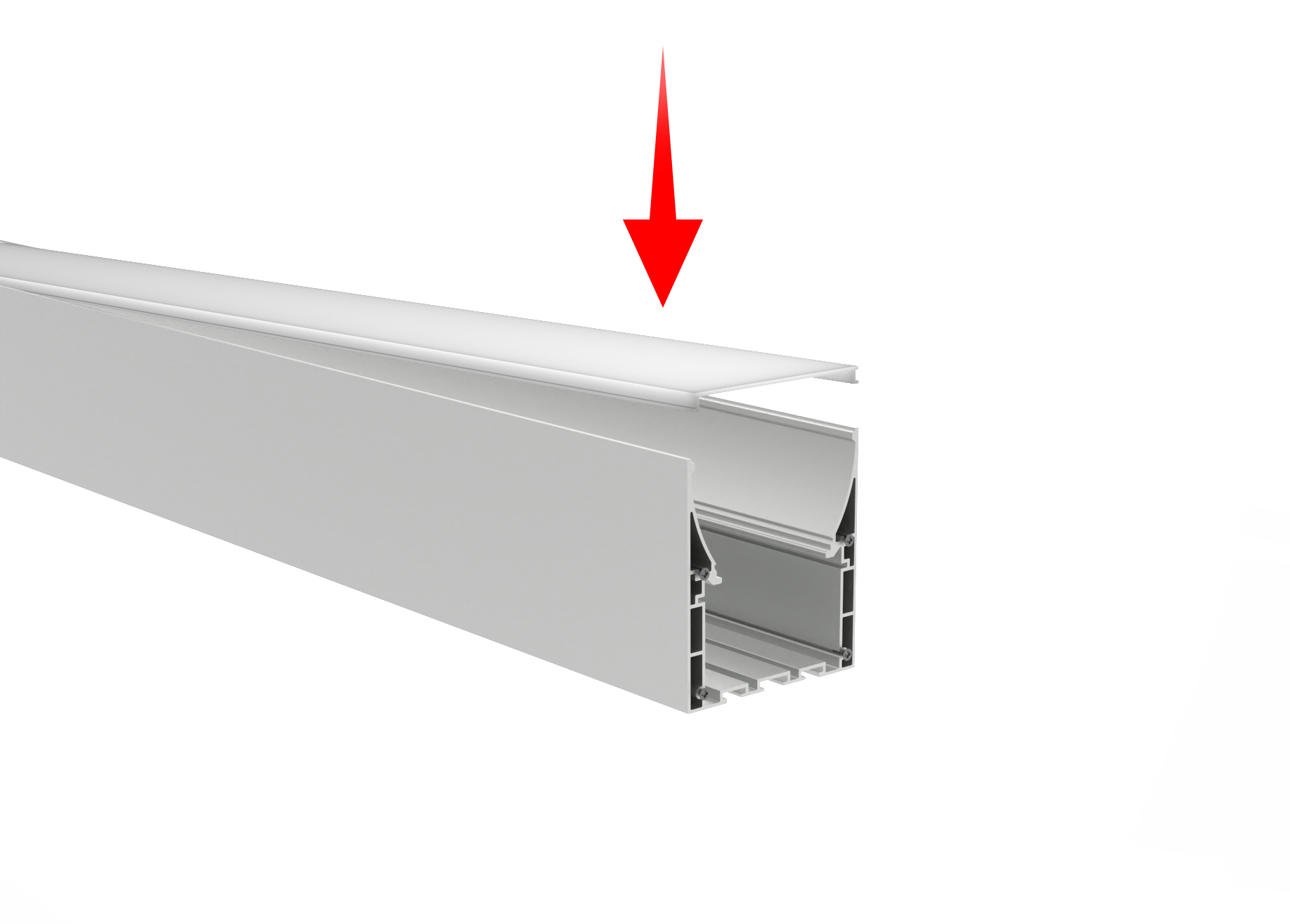
The strip adheres to the body, and plaster dust defeats the adhesive. Cap or tape the aperture during sanding. Dust in the channel is hard to remove and shows as a patchy line.
The cover is the last item. On a recessed body it clips into the groove and sits flush with the finished face. That is why slot depth follows outer height, not the flange.

How long can one be?
Our profiles ship in any length up to 4 m, cut to your size. A longer run uses more than one piece, joined with a connector or a mitre. The joint is mechanical, and it shows as a break unless you place it deliberately.
For a recessed ceiling run, set out joints at the same time as the slot. A joint in the middle of an 8 m line is visible; the same joint at a change of plane is not.
Can I install a recessed profile in an existing ceiling?
Yes, by cutting a slot and fitting the body into it. The body still needs something to fix to where no framing sits behind the cut. A backing rail must go in, which usually means opening more ceiling than the slot itself.
What board thickness do I need?
At least section height, plus whatever the fixing needs. A 12.5 mm body in 12.5 mm board leaves nothing for the fixing. The usual detail is a body shallower than the board, or a rebate cut into the back.
Does the profile have to be continuous?
No, though a continuous body runs straighter and leaves no joint to fill. Beyond 4 m, or at a corner, joints become unavoidable. Place them where a break reads as intended.
Can I use clips instead of screws?
Yes, and on an uneven substrate clips are the better choice, because they absorb variation that screws cannot. Load sets the limit: a wide body on a long run may need screws at intervals regardless.
How do I keep the plaster out of the channel?
Tape over the aperture before sanding, and cap the ends. Remove the tape before the strip goes in. It is a two-minute step that saves an hour of cleaning and a strip that will not stick.

We design and supply LED aluminum profiles and linear lighting — over 200 profiles with matched diffusers and fittings, serving customers in more than 100 countries since 2007.
Related reading

Send the strip width, the run length and the destination — we will match the profile, the diffuser and the fittings, and quote within 1 business day.
Start your inquiry