



Architectural lighting solutions, sorted by site problem
Catalogues are sorted by shape. Specifiers do not choose by shape — they choose by what is failing on site: a joint that cracks, a corner that goes dark, a glare complaint, a ceiling with 60 mm to give. Each section below starts from the constraint and ends at a part number you can order.
Five constraints that decide the section
If the brief names none of these, the profile is a commodity and price decides. If it names one, most of the specification is already settled — before a single luminaire is chosen.
What each one actually specifies
Making the profile disappear into plaster
A trimless detail is not a profile with a narrow flange. It is a body set into the board line, taped and skimmed, so the plaster returns to the aperture with no visible metal. What makes it work is the mud-in shoulder and how the diffuser is retained after the skim — not the finish.
Two things fail on site with cheap trimless bodies: the shoulder is too shallow to hold two coats and a skim, and the diffuser is pushed in from the room side, so it cannot come out after decorating without damaging the edge.


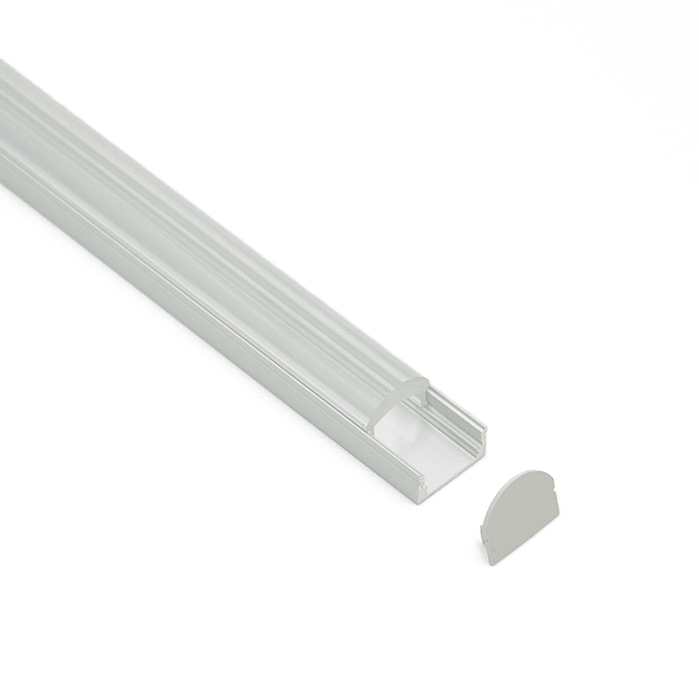
Turning the corner without a dark wedge
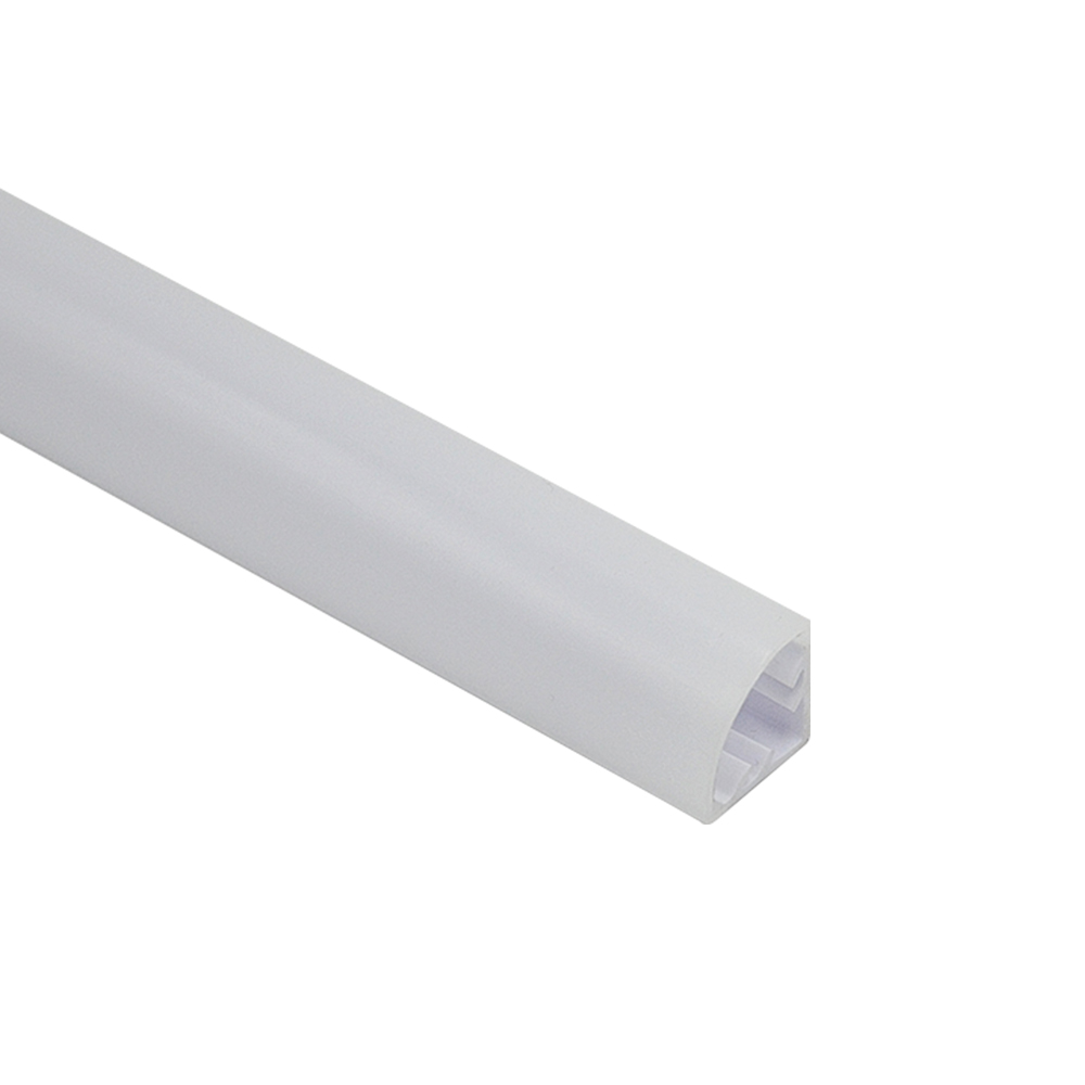
A straight body cannot follow an inside corner. The usual workaround — two runs mitred on site — leaves a visible seam and, more often, a shadow gap where the diffusers meet. An extruded corner section already turns through 90°, so the cover is unbroken around the return.
This matters most at the wall-to-ceiling junction, which is exactly where the specifier is trying to lose the luminaire in the first place.


One decision fixes both: cavity depth
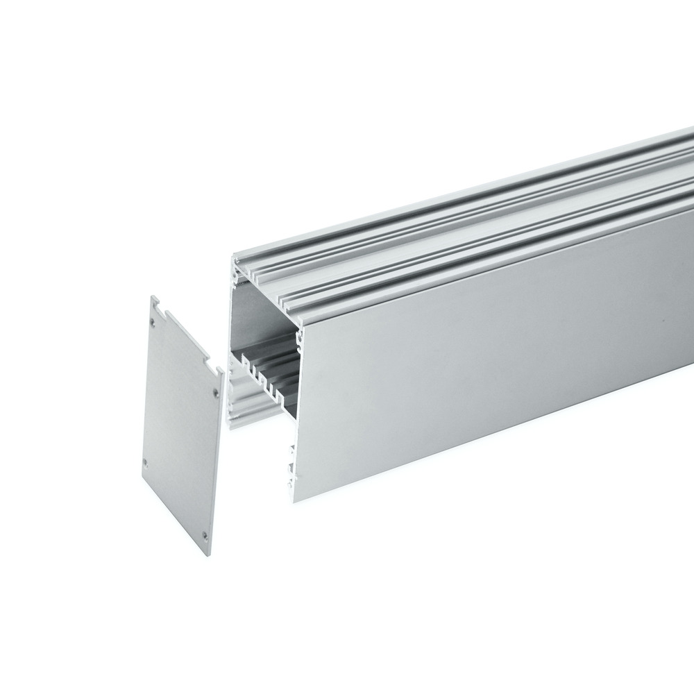
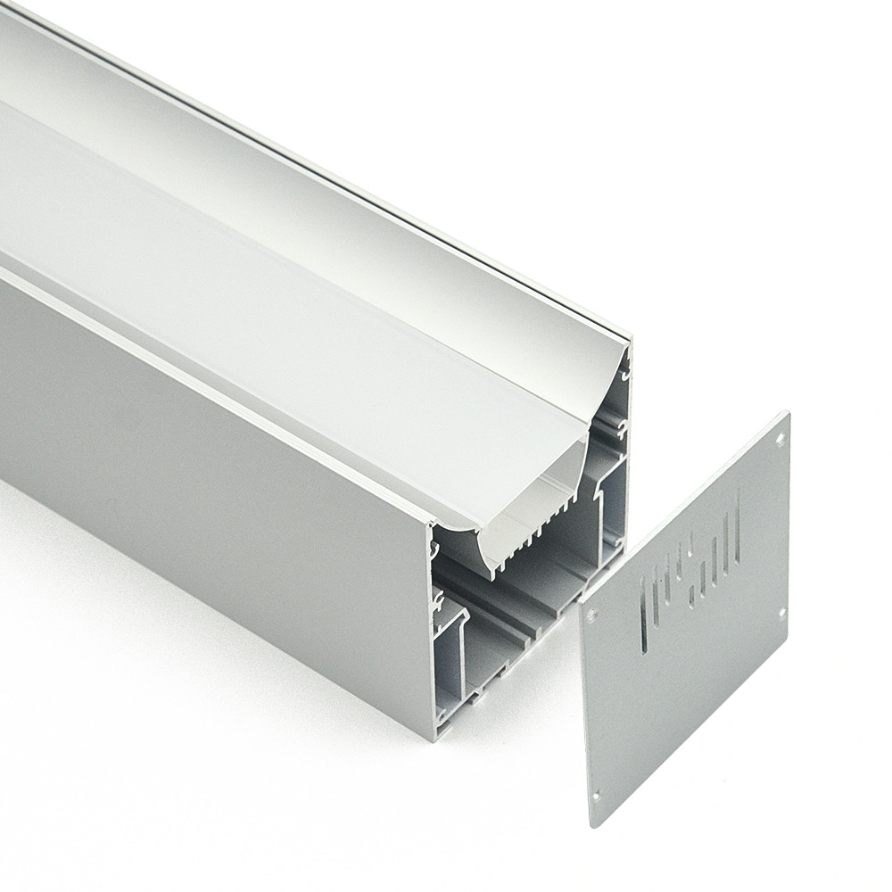
Glare in a linear detail is almost never a diffuser problem. If the diode sits close to the aperture, no cover hides it at a shallow viewing angle: the source has to sit behind the reveal. Dot visibility is the same ratio seen from the other side — diode pitch against the distance from strip to diffuser.
So a deep body with a narrow strip fixes glare and banding in one move, and it is usually cheaper than moving the whole job to COB. It also keeps the source replaceable, which a COB run is not.


When there is no ceiling to give
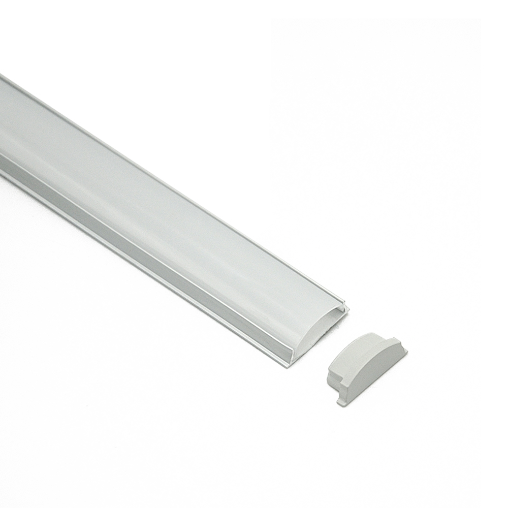
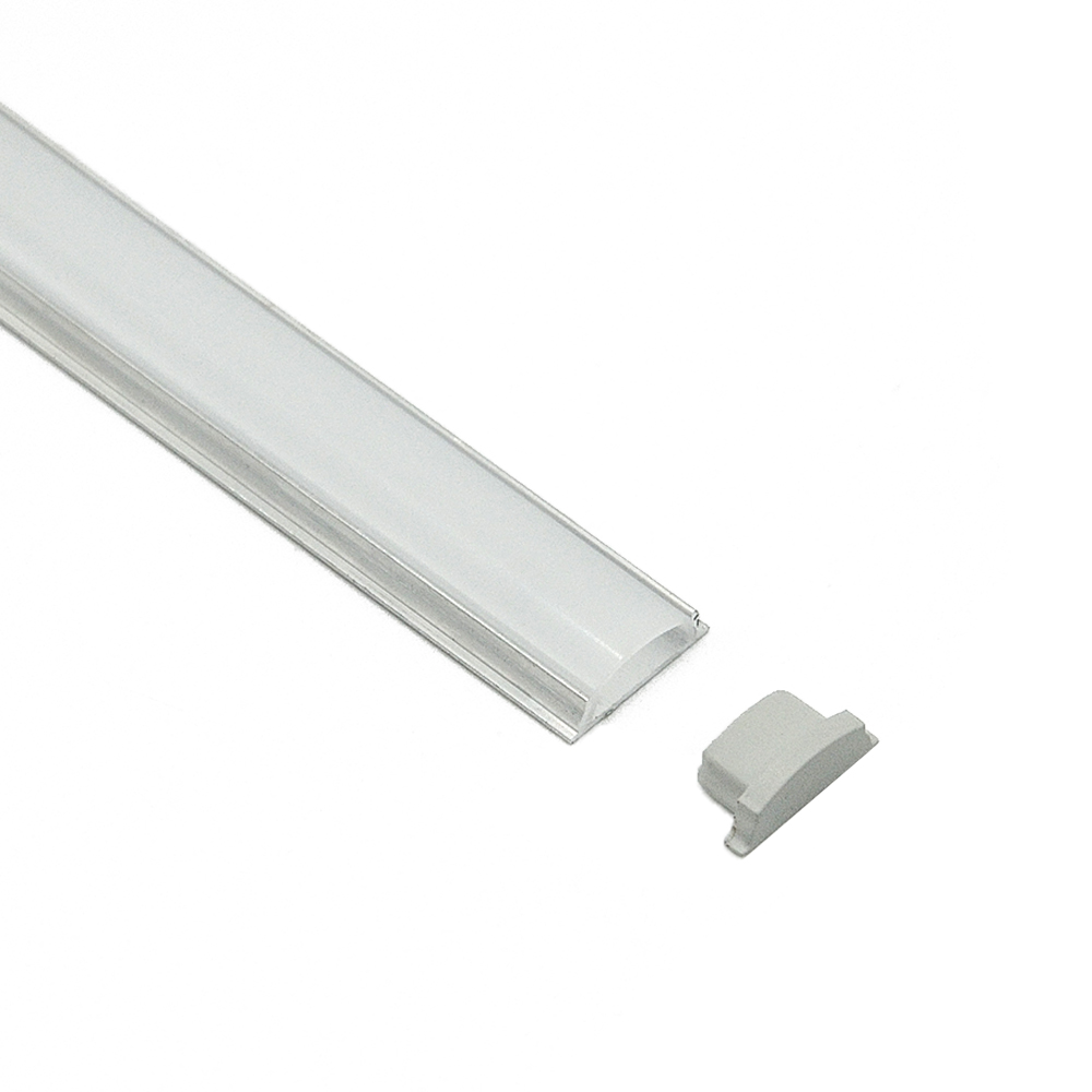
Slab edges, millwork reveals, retrofit ceilings with 30 mm of void — the jobs where a 5 to 9 mm body is the only thing that fits. The constraint is not aesthetic. Strip width shrinks with the body, so available output per metre drops with it.
Be explicit about that trade at specification stage. A 5 mm body takes a 5 mm strip; it will not carry the same output as a 23 mm body, and no diffuser changes that.

Sealing a run that lives outdoors
Water does not enter an aluminium profile through the section. It enters at the ends and at the cover joint. So the specification is about how the end cap is sealed, how the cover is retained along its length, and whether the body drains.
We do not publish an ingress rating for the profile itself. The rating belongs to the assembled fixture and depends on the strip inside it, the sealant used and how the end was closed. Anyone quoting an IP number for a bare extrusion is quoting the strip, not the profile.


The process map behind the section
A profile passes through six to eight separate plants before it reaches a site. Buyers ask which of them are ours. Here is the straight answer — because a specifier who is told we do everything stops believing the rest of the page.
 Partner
 Partner
 Partner
 Partner
| Process | Where it runs | What we still own |
|---|---|---|
| Billet extrusion | Partner plant | Die approval, first-article section check on the cooling bed, wall thickness and straightness on arrival. |
| Tooling and dies | Partner plant | Drawing release, die trials, and the decision on which sections are worth a die at all. |
| Anodising | Partner plant | Film thickness and colour against the approved sample; batch release or rejection. |
| Powder coating | Partner plant | Surface preparation, colour match, and re-work decisions on scuffs. |
| PC / PMMA diffuser extrusion | Partner plant | Profile-matched tooling so the cover fits the channel, plus a fit check on every batch. |
| Die-casting (caps, housings) | Partner plant | Tool design, casting sample approval, and dimensional check against the mating section. |
| CNC machining | Partner plant | Programme sign-off and first-piece verification before a run is released. |
| End cap and clip moulding | Partner plant | Mould approval and fit test against the profile it has to close. |
| Silicone neon body | Bought in | Supplier selection and incoming inspection only — we do not extrude silicone. |
| Strip and SMT assembly | Bought in | Specification of bin, pitch and CRI, and an incoming check on every reel. |
| Cutting and punching | Partner plant | Cut list, tolerance and the deburr standard. |
| Packing and export documents | Partner plant | Pack specification, carton marking and the document set. |
| Final assembly | Shenzhen, ours | Building up the run, end caps and seals, and the light-up test before anything is packed. |
| Inspection and test | Shenzhen, ours | All four inspection gates, and the release decision on every lot. |
Every process above is ordered by us and released by us. If a batch fails, the claim is with Helian — not with the extruder, not with the coater, not with the strip supplier. That single point of responsibility is the part worth writing into the purchase contract.
Twelve of the fourteen steps are partner plants or bought-in supply. The two that are ours are the two that decide whether the run leaves correctly: final assembly and inspection. That is deliberate — the end of the line is the only point where the whole assembly is in one place, under one set of hands, before it is sealed into a carton.
Every lot passes four gates: incoming, first article, in-process patrol and pre-shipment, sampled to GB2828, each releasing only against a signed record. A lot that fails has two exits — written concession or rework. Nothing moves on a verbal OK. The controlled documents behind those gates are public on the quality page, including the actual limits rather than a summary of them.
Four decisions that settle most of the drawing
Work through these in order and the section usually picks itself. Most expensive specification errors come from choosing a section first and discovering the constraint afterwards.
Send the constraint, not the product name.
Tell us the void available, the strip you intend to run, and what is failing on site. We will come back with the section, the cut list and the drawing — or tell you that aluminium is the wrong material for the job.
Send a project brief →